
August 8th is Happy Hacking Day in Japan. On that day, an article (in Japanese) was published at www.gniibe.org, to resist bulk surveillance.
This article is English translation of the article. The purpose of this article is to make own own TRNG (True Random Number Generator). A bit of soldering is required, but it's not that hard, even for a beginner of electronics. We use the board "STM32 Nucleo F103RB", which is cheap and good. Thanks to Kenji Rikitake to enhance Chopstx to support of this board.
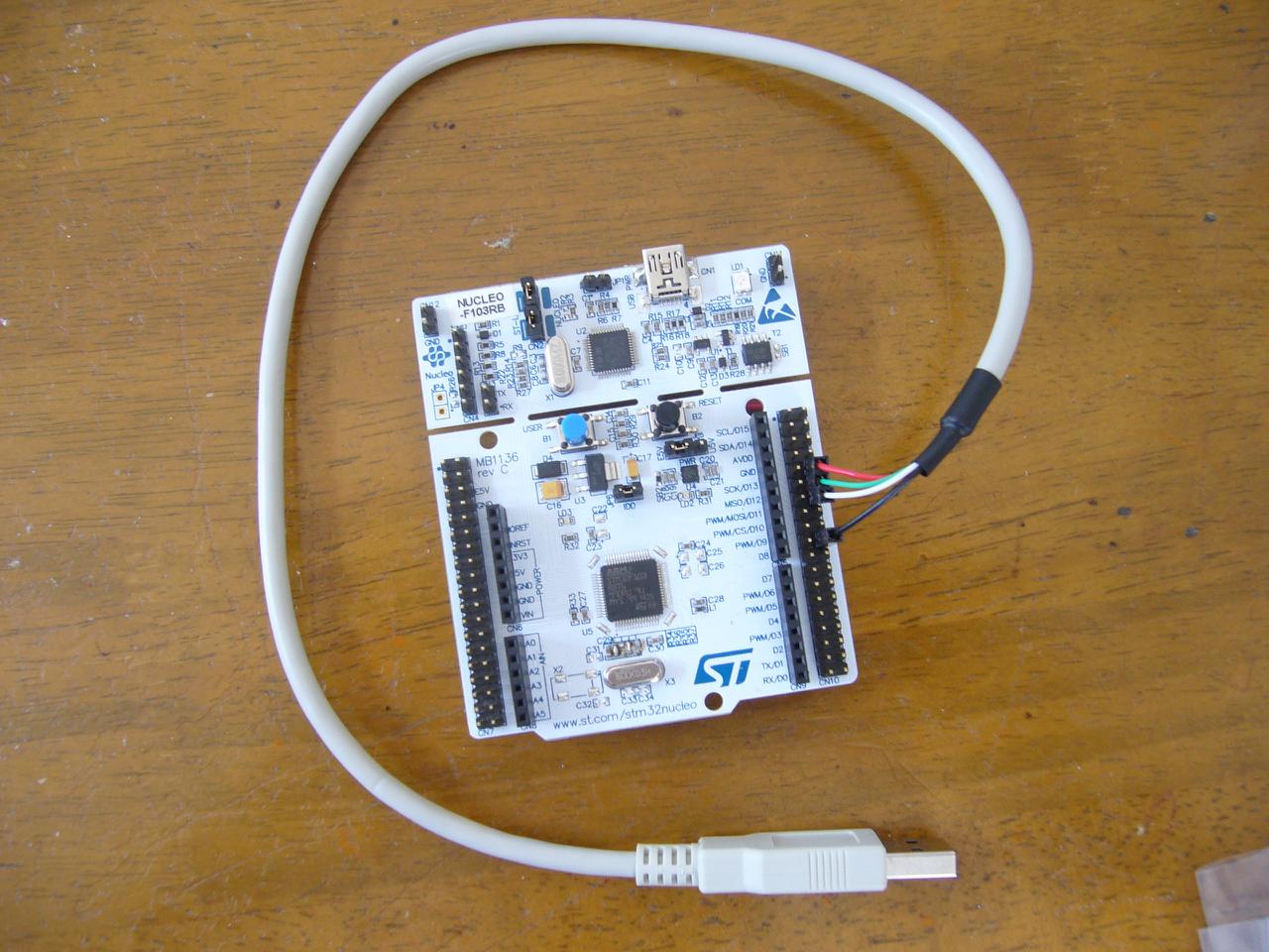
Photo of the final result
STM32 Nucleo F103RB consists two parts: the dongle (ST-Link/V2-1) and the target board of STM32F103.
In this photo, the dongle (ST-Link/V2-1) is not separated yet, it will be separated when we use only the target board. (It is possible to run the target board with power from USB cable, not separeting the dongle.)
Tools to make
- Soldering Iron
- Nipper
- Utility knife (when the board will be seperated)
Parts
| Parts | Price (JPY) |
| STM32 Nucleo F103RB | 1500 |
| USB Cable (ex. comon AM-MB) | 250 |
| 8MHz XTAL | 150 |
| 1.5k Ohm resister, wire, solder | alpha |
| Total | 1900 + alpha |
How To
(1) Connecting 8MHz XTAL (X3) (Front Side)
Since XTAL is not connected to the target board, we add it, cut the legs of XTAL and solder it.
The target board has lands for R35 and R37 which are intended to connect SMD parts of 0 Ohm resisters. We don't need to buy 0 Ohm resisters, but, just solder it to make solder bridge. If it's difficult to make a bridge, you can use XTAL's legs remained.
I mistakenly made a solder bridge for R34, but this is no problem for our use.
By its design, it is intended to put capacitors of C33, C34 to stabilize oscillation, but it is OK without them.
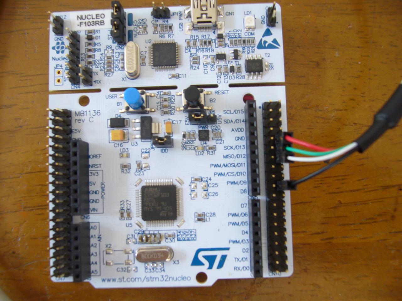
(2) Connecting USB Cable (Front Side)
Coloring of USB cable is: Red 5V, Green D+, White D-, Black GND. We connect USB cable to CN10.
We connect Red 5V to pin10 of CN10 which is NC (NC stands for "not connected" to any pin of MCU). We will connect this pin to E5V (external power source) in back side.
We connect Green D+ to pin12 of CN10 which is PA12 (USB DP).
We connect White D- to pin14 of CN10 which is PA11 (USB DM).
We connect Black GND to pin20 of CN10 which is GND.
The cable I use is avaiable from comon.jp as the part number "AM-MB". It is usually used with mother board of PC.
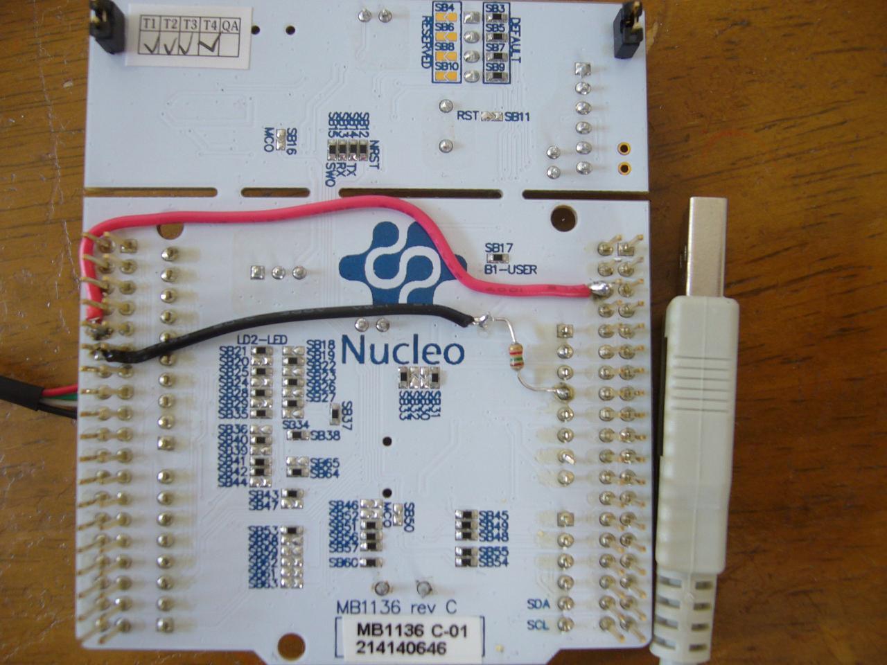
(3) Connecting a resister and power (Back Side)
In the back side, we pull up the signal of USB DP to 3.3V. We connect USB 5V to E5V (external power source).
For the former, we solder 1.5k Ohm resister to pin12 of CN10 by wire (I use black wire) and solder another side of the resister to pin4 of CN6.
For the latter, we solder pin10 of CN10 to pin6 of CN7 by wire (I use red wire).
I use thick wire to take a photo, but you don't need such a thick wire.
(4) Writing firmware
Connecting the dongle to PC and write the firmware of NeuG USB Device by OpenOCD.
(5) Changing Setting of JP5
Change JP5 setting to E5V (Use external power source), and use the target board by the power fromUSB cable.
In fact...
You can easily find that the dongle also uses STM32F103. So, it is possible to change the firmware on this MCU and let run as NeuG USB Device, if you have another SWD debugger.
The specific detail is left to readers.